Manufacture-Ready Molded Parts
And the Tool to Make Them
From the part to the mold, CoDesigner automates the expert-bound molding and tooling work: draft, walls, shrinkage, warpage, flow, features, and computes geometry that comes out of the tool exactly as designed.
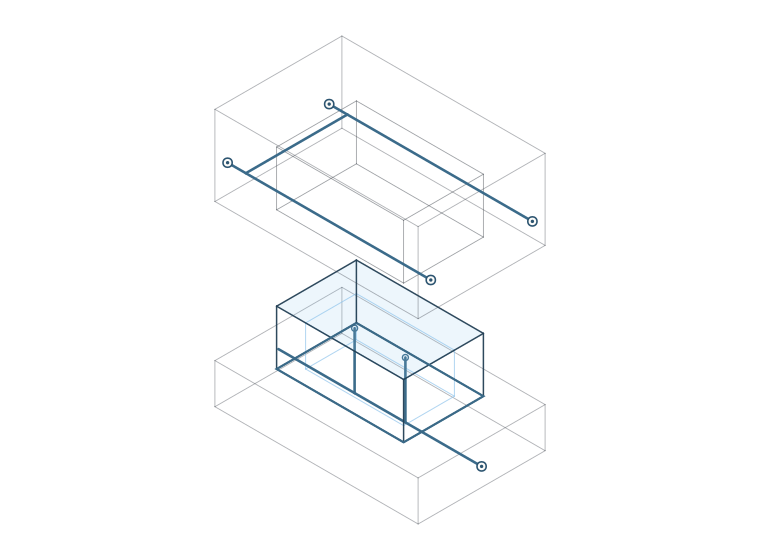
> cavity & core > cooling computed > tooling-ready
drag to rotate
Physics-Driven Molding, with DFM Respected from the First Step
CoDesigner optimizes the geometry for the physics of molding, flow, shrinkage, warpage and release, while respecting your tooling and DFM from the very start, not bolted on at the end. Your engineers keep the intent; CoDesigner automates the work in between.
What CoDesigner Handles, From the Part to the Mold
The manual, expert-bound molding work: automated where the physics is clear, proposed where judgment matters, and always left to your people where it should be. This is the list to scan if you are wondering whether we handle your part.
The engine computes and writes the geometry where the physics is unambiguous and the result is checkable.
We compute the change and show it with the reasoning. Your engineer approves it and applies it.
Design intent, functional surfaces and final sign-off stay with your team, by design.
- Tooling & Molding Strategy
- Part orientation, split plane and parting lines, where cores and sliders are needed, and gate placement, worked out together to minimize the number of directions and tools the part needs.
- Draft Angles
- Automatic on smooth, organic geometry, where the surface itself defines the answer, in production today on parts released to market. On feature-dominated parts (screw towers, snaps, contact faces) draft carries design intent, so there we compute and propose rather than decide. automatic on organicguided on features
- Roundings & Chamfers
- Automatic rounds on smooth, organic geometry, computed from the shape and shipped in production, respecting what the cutter can actually reach. A radius driven per point by stress and flow is not in production yet.
- Wall Thickness
- Driven by flow, shrinkage and warpage rather than a single shell number, computed on our own flow solver. our flow solver
- Weld-Lines, Sink & Warp
- Avoid or place weld and knit lines, sink marks and warping with respect to gate, flow, geometry and loads, so they land away from critical areas.
- Feature Handling
- Custom recognition and handling for snaps, undercuts, ribs, bosses, screw towers, threads, and deep or narrow features.
- Mold Side
- Mold compensation, cavity layout, cooling layout and ejectors, so the geometry comes out of the tool exactly as designed.
- Engineering Depth
- Stiffness, strength, vibration, thermal, flow and structure, optimized together with manufacturability rather than after it.
We Wrote the Flow Solver, So We Can Run It Inside the Loop
A full 3D solver, written from the Navier–Stokes equations up. Because we own it, we can run it thousands of times while the geometry is still changing, instead of once as a check at the end. Fill, gate, weld lines and venting, on your part.


// on one real production part our solver predicted weld lines a sophisticated specialist simulation tool had not surfaced, anonymized. Every result is checkable against your own tools, for example Moldflow or Ansys.
Bring a Real Part and a Real Bottleneck
Bring a real part and a step in your design, development or manufacturing process that is slow, repetitive or reserved for one or two specialists. We tailor the CoDesigner modules to your case and show you the potential for automation and scalability. No synthetic demos.
Bring a Real Part & a Bottleneck
An injection-molded part, and the step that takes the most expert time.
We Tailor the Modules
We adapt CoDesigner to your case and run it on your own geometry.
You See the Potential
Real before/after geometry, plus where it automates and scales.